
CURIOSITIES
************************ 1848 ***********************
French Sewing Machine
************************ 1853 ***********************
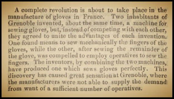
Manufacturing of Gloves
Grenoble - France
************************ 1854 ***********************
************************ 1866 ***********************
William Thomas


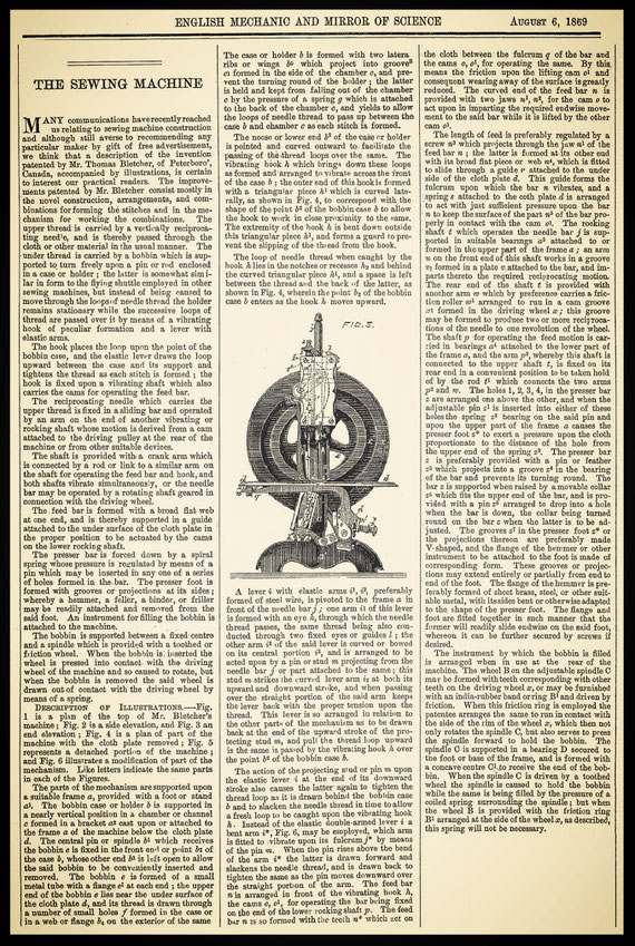
THOMAS BLETCHER
"IMPROVEMENTS IN SEWING MACHINES"

PATENTS
GB 936 (March 27, 1869)
US 105.631 (July 26. 1870)
************************ 1871 ***********************
ELECTRO-MAGNETIC SEWING-MACHINE
Our engravings illustrate the invention of Stevens and Handy, of San Francisco, California, patented in 1871. It consists in a novel arrangement of the apparatus which forms the motor, and which, according to the inventors, enables greatly increased results to be obtained from the coils with the same pulley power. It will be seen that the armatures drive the needle-bar directly, without the intervention of levers or other mechanism; while the feed-movement is also very simply arranged, and is likewise driven directly from the armatures.

Figure 1 is a side-view of the essential portions of the apparatus and Figure 2 is a vertical transverse section of one pair of coils, and also shows the feed motion.

The following description applies to the two figures. A is a case which rests upon the top of a cabinet and serves to conceal portions of the machinery ; it also serves as a table for the work : two pairs of coils, B and C, are placed so that their upper ends stand just within or at the bottom of the case A, to which they are secured ; these coils are placed at such a distance apart as to admit of the working of an oscillating beam D, which is supported on standards over their central line ; this beam is balanced so that the magnets or armatures of one pair of coils are connected to one end, and those of the other pair to the opposite end. The coils are constructed as shown in Figure 2, being formed of insulated wire, coiled to suitable size, leaving an opening through the centre sufficiently large to admit the magnets and their armatures. The coil is surrounded by an iron cylinder, which greatly increases the power of any given coil. Outside this cylinder another coil may be placed, and this, in turn, enclosed by another iron cylinder; this gives good results, but not so great, in proportion, as are obtained from a single coil and cylinder, which the inventors consider sufficient. The magnets b and c are made, as usual, of soft iron, and each pair of bars united by a plate d across the top ; or they may be formed in one piece, as a U magnet reversed. The magnets extend down into the coils about two thirds of the depth of the latter, and the armatures f arise from the bottom, about one third of the height of the coil, this construction also adding greatly to their power. The oscillating beam D has one end connected to each of the plates d, and from some convenient point on its length the needle-bar E arises and extends forward to the table of the sewing machine, over which the work passes. From the centre of the beam D an arm F depends, and as the beam oscillates from the alternate attraction of the magnets, at either end, this bar vibrates from side to side, striking alternately pins on a vibrating bar i, which is pivoted at the bottom, and which is also caused to move from side to side. This alternately forms and breaks contact with the two pole changers g and h, and causes the pairs of coils B and C to act alternately, thus moving the magnets b, c, the beam D, and the needle-bar E. The feed-motion is operated in the following manner : A bar or arm V, extends forward from the end of the beam D, and partakes of its oscillations. Two standards m, m support a shaft G, which lies parallel with and a short distance from the arm V. At one end of the shaft is an arm H, which projects over the arm V, and as this oscillates it moves the arm II up and down, thus partially rotating the shaft G back and forth at each oscillation. A small crank arm o is fixed to the opposite end of the shaft G and the upper end of this is so attached or connected to the feed-plate p as to move it forward and back, raising it at the proper time. If found more desirable, two or more pairs of coils could be connected with each end of the oscillating beam D, but the inventors have found one pair sufficient for all ordinary purposes. In order to prevent noise, and diminish the force with which the magnets and armatures would meet, the arms V pass through a case K, within which are placed elastic cushions, above and below, and against which the bar strikes as it moves. The inventors also patent a form of " switch," by means of which they are enabled to control the battery power, employing either two, four, or any number of cells required. Although the invention is here shown as applied to a sewing-machine, it is really capable of being employed in working various other machines.
The Nottingham Sewing Machine
In December, 1844, a Nottingham inventor made a sewing machine without knowing it. Mr. Foster, the inventor, was a very young man, only nineteen, when he first contrived his machine, and in conjunction with his moneyed partner, Mr. Gibbons, brought it into practical use at the time mentioned. The patent, which was taken out, was for " working ornamental designs on lace or net, and other fabrics, by machinery, in such manner that two threads are caused to loop together, one thread passing through the fabric, and the other looping therewith on the surface without passing through the fabric." It is not necessary to describe the machinery by which this was done. Suffice it to say there were two needles, one on each side of the fabric, the one curved and the other straight; there was also a needle and shuttle arrangement. After giving a description of this machinery, the specification of the patent goes on to, describe other machinery for "sewing thread, yarn, gimp, cord, or fabrics in pattern, on the- surface of fabrics". " If desired," it adds, " a second fabric may be placed on the fabric to be ornamented, and when sewed together, the former may be cut away between the figures or patterns." If this was not a true sewing machine what is ? After Howe's invention became known in England, Foster altered his machine, and made a sewing machine of it, while even as it was it was sufficient to invalidate Howe's (or Thomas's) patent, parts of which were accordingly disclaimed.
By H. T. Wood. The Sewing Machine Gazette 1884
Foster actually was Fisher,
GB 10.424 John Fisher & James Gibbons December 7, 1844
************************ 1876 ***********************
HAND SEWING MACHINE

************************ 1879 ***********************
AMERICAN PATENT OFFICE REPORT

************************ 1881 ***********************
A NEW FUR SEWING MACHINE

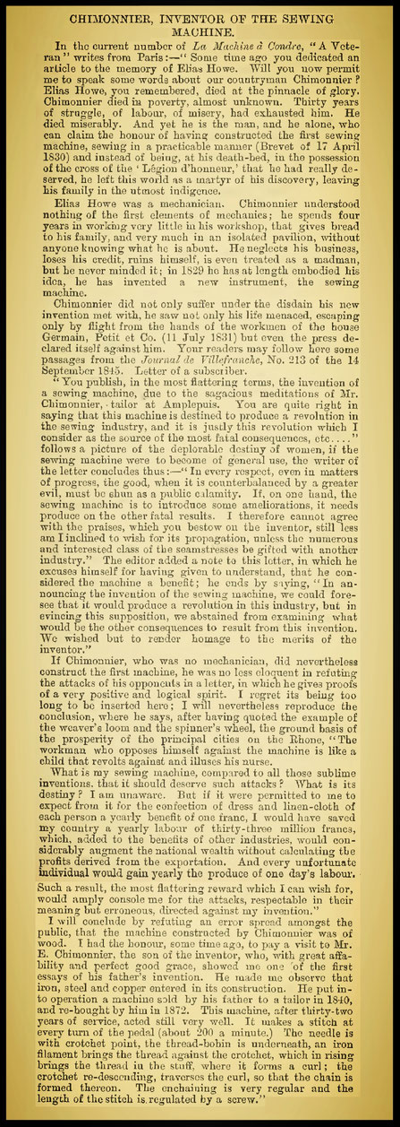
C...HIMONNIER
INVENTOR OF THE SEWING MACHINE
************************ 1893 ***********************
************************ 1904 ***********************

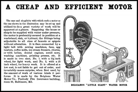
************************ 1910 ***********************
WHERE DID YOU SEE THIS MACHINE?
The sewing machine shown here, incomplete, in order to most fully disclose its striking feature, is not of the oldest, hardly of the second generation; yet its short life in the market was before the majority of the men of to-day came into the trade. The $ will be given to the one who can tell most about the machine, its invention, its inventor, its history or any facts connected with it. The offer is not confined to subscribers; it is open to all, with no cost, no restrictions. Tell what you know of it in your own way. This is real money. Mail answers within a month from this day of issue.
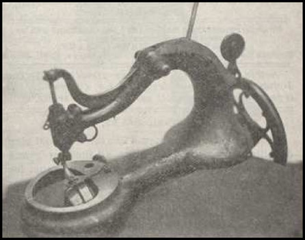
THE WARDWELL
Descriptions by Correspondents of a Curious Early Machine
The identity of the machine you ask for in your issue of June 25th is the Wardwell, invented by Simon Wardwell, about 1876 and made at Colt's Armory, Stamford, Connecticut. It made a lockstitch from two commercial spools. The take-up was on top. It was a lever, pivoted at one end and worked by a stud and roll in a face cam, fast to the hand wheel. The lower spool was on a vertical pin. On the end of the shaft was a revolving hook, similar to the present rotary shuttle machines. It had the usual four motion feed. The head was on a swivel and could be turned at any angle on the table. The fly-wheel of the stand was on a turn table so that the belt would always be in position. The needle bar was straight, the needle had ball on end and a slotted hole in the bar which allowed the ball to fasten the needle to the bar without the aid of a screw.
R.H. Paddon, 438 Railroad Avenue, Brooklyn, N.Y.
***
Sewing Machine Times can add but little to the above descriptions of the Wardwell sewing machine, which was in the market for a short time, attracting attention through its originality. It differed in nearly every feature from the accepted models of its day and met some of the then prevailing views of what a sewing machine should be. Among the peculiarities not mentioned above, was the large tubular presser-bar, through which the needle-bar worked and had its bearings. The casting for the head was in two shell-like halves, bolted together, enclosing the works. The circular bed-plate was about 5 inches in diameter, from which the size of the head may be judged. Simon W. Wardwell, who then wrote his name as Junior, was a resident of St. Louis when he took out the half-dozen patents covering this machine, in the year 1871-'77. He has since, to the present time, been known as an inventor of sewing and other machinery. Nearly one hundred patents have been granted to him in lines allied to that sewing and half as many in other branches of mechanical art, spinning, weaving, braiding, knitting, &c. Mr. Wardwell has resided for many years at Providence, R. I., engaged in manufacturing and in the developing of his many inventions.
Mr. Paddon's description, which was the first in hand, being most fall, will take the $. To the others who have kindly written appreciative thanks are given.


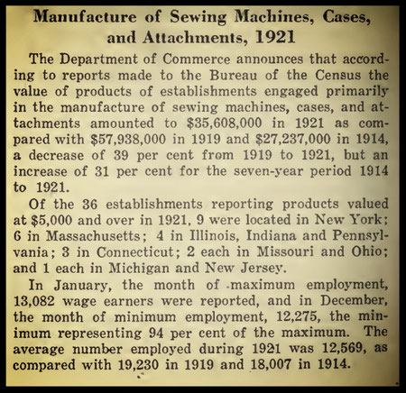
************************ 1921 ***********************
MANUFACTURE OF SEWING MACHINE
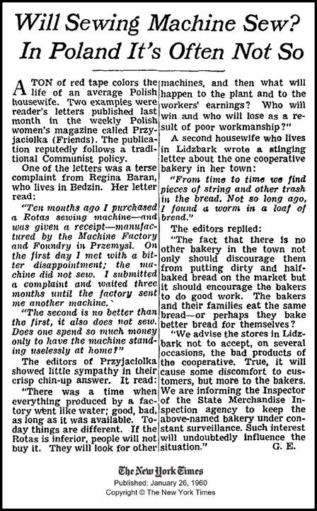
************************ 1960 ***********************
As reproduction of Historical artifacts, this works may contain errors of spelling and/or missing words and/or missing pages, poor pictures, etc.